I. Overview
The Intelligent Reactive Power Dynamic Compensation Device adopts power electronic switching capacitor technology and direct sampling technology for random reactive power. It features surge current resistance, anti-interference, reliable operation, and switching overvoltage resistance. It is particularly suitable for reactive power compensation in urban and rural power grids, rapid compensation in oil fields, and reactive power compensation in internal power grids of industrial and mining enterprises. It can be installed on the electric pole of outdoor pole-mounted transformers with a voltage level of 10/0.4kV or 0.6/0.4kV, and has a wide range of applications.
Meanwhile, this device is equipped with the function of real-time monitoring and displaying three-phase power parameters, which can display three-phase voltage, current, power factor, frequency, active power, reactive power, and harmonic distortion in the circuit at any time. It is provided with an RS485 interface and supports functions such as MODBUS/JBUS interfaces, enabling communication with upper computers in accordance with protocol specifications.
In addition, the XZW Reactive Power Compensation Device is equipped with short-circuit protection, overload protection, and leakage protection functions, and also has the characteristics of an integrated power distribution cabinet. This device is a domestically leading contactless dynamic reactive power compensation device.
II. Operating Environment Conditions
- Ambient Temperature: -25℃ to +40℃, with the 24-hour average temperature not exceeding +35℃;
- Relative Air Humidity: When the maximum temperature is 40℃, the relative humidity shall not exceed 50%; higher humidity is allowed at lower temperatures;
- Altitude: Not more than 2000 meters;
- Installation Site: It shall be installed in a place free from severe vibration, impact, and corrosive gases.
III. Main Technical Parameters
- Rated Operating Voltage: 400V;
- Rated Capacity: 50kVA, 80kVA, 100kVA, 160kVA, 200kVA, 250kVA, 315kVA, 400kVA, 600kVA;
- Compensation Capacity: 225kVar, 23kVar, 45kVar, 60kVar, 675kVar, 90kVar;
- Compensation Effect: ≥0.95;
- Compensation Method: Three-phase balanced compensation, three-phase split-phase compensation;
- Switching Mode: 1-2, 1-2-2, 1-2-4-8;
- Switching Delay Time: 10S – 100S;
- Circuit Protection Functions: Short-circuit protection, overload protection, phase failure protection (for three-phase balanced compensation);
- Leakage Protection Function: Phase discrimination and amplitude discrimination (phase selection);
- Display and Monitoring Functions: (1) Power factor; (2) Current; (3) Voltage; (4) Transformer ratio; (5) Reactive power threshold; (6) Delay; (7) Overvoltage threshold; (8) Three-phase voltage (optional); (9) Three-phase current; (10) Frequency (optional); (11) Active power (optional); (12) Reactive power (optional); (13) Active energy (optional); (14) Reactive energy (optional); (15) Total harmonic distortion
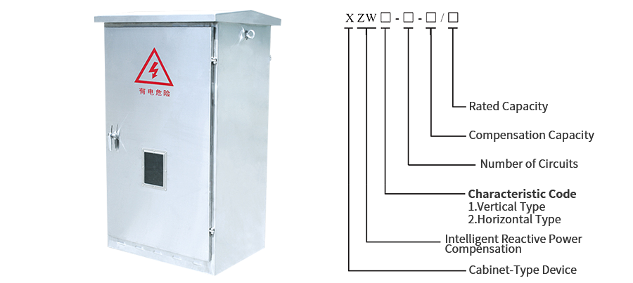
- Outline Structure: Vertical/horizontal type; full stainless steel shell/steel plate plastic-sprayed shell.
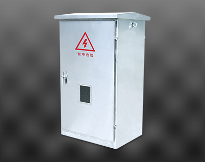
IV. Structure
The cabinet structure is available in vertical and horizontal types, featuring a fully enclosed design with front and rear doors. A waterproof groove for water resistance is provided at the joint of the door frame. The top is equipped with a brim-shaped top cover and air vents; a wire mesh is installed to prevent the intrusion of foreign objects. The power supply part enters through the waterproof wire inlet hole at the upper part, and the wire outlet hole at the bottom of the cabinet is used for wire outgoing. The cabinet has anti-rust, waterproof, and protective properties, with an protection class of IP54. Main Working Principles and Operation:
1. Control principle of three-phase balanced compensation; (Omitted)
2. Control principle of split-phase compensation; (Omitted)
3. Power factor controller, panel operation, parameter setting, and working condition selection;
As shown in the right figure:
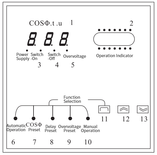
(1) LED Display: Shows power factor and preset parameters;
(2) Operation Indicator: Displays the working phase of the capacitor bank;
(3) Switch-on Status Indicator: Strobing (indicates that the capacitor switch-on will be executed);
(4) Switch-off Status Indicator: Strobing (indicates that the capacitor switch-off will be executed);
(5) Overvoltage Status Indicator: Light on (indicates that the overvoltage switch-off of the capacitor bank will be executed);
(6) Automatic Operation Indicator: When lit, the device is in automatic operation mode;
(7) cosΦ Preset Indicator: When lit, the LED display shows the cosΦ preset value;
(8) Delay Preset Indicator: When lit, the LED display shows the switching delay preset value;
(9) Overvoltage Preset Indicator: When lit, the LED display shows the overvoltage threshold preset value;
(10) Manual Operation Indicator: When lit, the device is in manual operation mode;
(11) Function Selection Key: Cycles through the functions from item (6) to item (10);
(12) Increment Key: Used for manual switch-on of the capacitor bank and parameter modification;
(13) Decrement Key: Used for manual switch-off of the capacitor bank and parameter modification;